Having a layout sheet show a floorplan at 1/4"=1' scale is the industry norm. However, if you want to have a full color with materials shot of the floor plan, it's a little harder to get it to the layout sheet at scale. The reason is, a full color shot with flooring & countertop materials when created is a jpeg view, not a vector view. There are some steps you can take to get it to scale, and I list them in detail on the following video:
The video quality uploaded to this blog is a little lousy, so to see it in much better definition, click here: http://indyblueprints.com/free.aspx
Wednesday, April 27, 2011
Thursday, October 28, 2010
Showing New Addition Framing On Existing Home
When doing a room addition design, I like to show the framing of the new addition, sitting with the existing home. This is not a critical part of the Construction Drawings (CD's), but it really gives them some "Flair" if you know what I mean. After all, I don't consider my CD's for a new home or remodel project "a simple or basic blueprint". I like to produce a set of drawings that uses all of Chief Architect's 2D & 3D capabilities, to not just show the plan, but show it in a creative & attractive way:


Creating this view is not that easy, if you don't know how. There are a couple of ways to do it, but I just discovered a new, fairly quick way. The method I had used in the past, was using custom layers & layersets, but I found it was very slow. My new method uses symbols, and shaves some time off.
Step one:
Of course, is to draw the existing home, and name the file "Jones As-Built":

Then Draw the new addition on the house: 

The next step involves creating a couple of new plans by doing a "save-as". Take this finished plan and do a "File>Save As" and change the file name to "Jones room addition without house". Next step is to auto-build all the framing in the house. At this point you can start deleting all portions of the old house, so nothing is left except the new addition: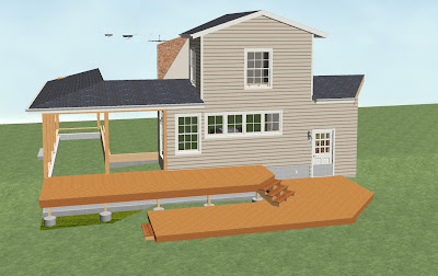

Next, take a 3D Framing Overview, and turn off the terrain and deck planking:

Here is where the magic happens; From this view, you can go to the upper toolbar, and click on "Tools>Symbols>Convert To Symbol". This will turn everything that's showing in the view into a symbol. You can check "Add to Library" if you like, but it's not necessary.
Next, go back to your "As-Built" plan, and while in floor plan view, go to the upper toolbar, click on "Tools>Symbol>Get Last Symbol", and click in the plan. This will place the symbol in your plan. Now all you have to do is to adjust the height & location, by "Ctrl" dragging it into place, and you're done:

Friday, June 18, 2010
Interior Raytrace Lighting Chief Architect X3
Let me start off by saying that I am not an expert in lighting, but with the help of some of the Chief Peeps, I have at least been able to get a working knowledge of how to get lighting set up for interior raytraces, in Chief’s new raytrace engine. The purpose of this article is to enable you to get a really nice raytrace, in under 10 minutes. There is a lot more involved in getting a stunning raytrace, but that’s also something you can accomplish in Chief, with some effort.
First thing you want to make sure of, is that all the lights in your model are turned off! Do this by going into “3D>Lighting>Adjust Lights”. Select the first light, scroll down to the last light, hold your shift key and click on the last light. This will “Group Select” all the lights at once. Then just click on the check mark in the box of any light fixture, and this will turn them all off at once. When you set up your raytrace, you will turn on just the lights in your scene. The reason for this (I learned the hard way) is if you have 165 lights on in your model, a “Quick” raytrace might take 7 hours, and if you only have 6-8 lights on, it will drop down to 5-6 minutes. Chief’s new raytracer will not be drastically slowed down by a complicated model, but it will be drastically slowed down by too many lights, even if they are on a different floor.
Before we adjust the light type, you should open your light fixture, go to the Material tab, select “Bulb”, click on “Plan Material”, select “Lighting, White”. Next, click on “Edit”, go to the “Properties” tab, Under “Material Class”, make sure “General Material” is selected, and move the slider for “Emmisive” all the way up to 100%. This will make the bulb on the light look like it is ‘glowing’ in a raytrace view, and look more like an actual light.

Next, some info about light source types. When a light fixture is placed in a plan from the library, it does not necessarily have the best settings for an interior raytrace, but so far, I have noticed they are set up to get a pretty good scene for renders. Any light you get from the library can be set to 1 of 3 different types of light source, regardless of what kind of fixture it is. This information can be found and adjusted by selecting a light fixture, either in plan view or 3D view, open the item, then go to the “Light Data” tab in the Dialog Box.
Chief has 3 types of light sources;
• Point light
• Parallel Light
• Spot Light
Point lights give a pretty even spread of light in every direction. They are the best type of light to light up a room in a render view, but I don’t like them at all in a raytrace view, because they give a big bright spot on the ceiling all around the fixture, like the light was shining back up towards the ceiling.
A Parallel light won't do you any good inside (aside from through openings). Parallel lights are infinitely far away. So, I won’t choose a parallel for an interior raytrace.
Spot lights seems to work the best for interior raytraces, but they require some adjustments.
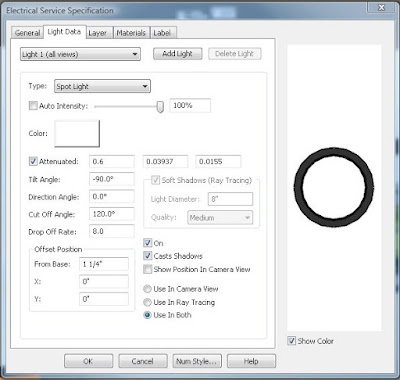
Of course the first thing you want to do is to hit the drop down on “Type”, and select Spot Light. Next, Un-Check “Auto Intensity”, and move the slider up to 100%. This might be too high in certain scenes, and if so, you can back it off to around 80%.
The next item to adjust is the “Cut-Off Angle”. A Cut-Off Angle of 5º will give a narrow beam of light straight down to the floor. A Cut Off Angle of 60º will give a much wider beam of light, more like a real spotlight:

So far, for interior raytraces, I prefer to set the Cut Off Angle at 120º.
The next item we want to look at is the “Drop Off Rate”.
Quote: Dermot Dempsey “The Drop Off rate for a spot light controls how quickly the light drops off from the center of the cone to the outer edges of the cone.
Try experimenting with the values to see the effect. Place a single spot light in a room pointing down and leave the cut off angle at 60 degrees. A drop off of 7.5 means the light will drop off fairly quickly as it gets to the outer edge of the cone. Try setting it at 0 and you will see the same light at the outer edge as you do at the center. This will look more like the kind of spot light used in theater then in houses. Chances are that you will get the best effects with something greater then 0 but less then the 7.5 default.”
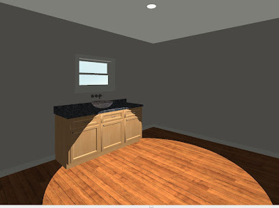
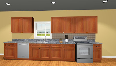
Here’s my explanation: In the pictures below, the first picture has the Drop Off Rate set at zero. This means that at the outer edge of the circle of light coming from this fixture, it has a clear (harsh) edge like a flashlight in the dark with a concentrated beam:
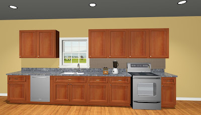
This next picture has the Drop Off Rate set at 2.0. This gives a much softer edge, but still allows you to see that the light is actually giving light to the scene, and a much more realistic look.
This third picture has the Drop Off Rate set to 6, which I think is too much, because the edge definition of the light is completely gone, so you don't get a feeling that these lights are real:
So, in this particular case, I like the Drop Off Rate set to 2.0.
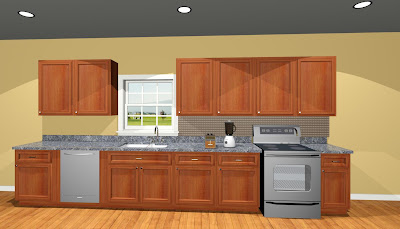
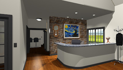
This is not always the case, in some scenes, you will need to bump the Drop Off Rate all the way up to 10 or more to get soft edges with the lights. Here’s an example; In this office scene, The first picture has spots set with a Drop Off Rate of 2, and the edges on the light beams is too harsh. The second picture has the Drop Off Rate set at 8, and it looks much better:

However, this scene is also affected by the amount of light coming from the other fixtures & light sources. When you have additional light sources in the room, the edges of those spot light ‘beams’ get washed out a little bit, so you have to keep that in mind; if your edges are too sharp, and raising the Drop Off Rate doesn’t get it where you want it, you may need to add additional light sources.
Which brings me to my next subject:
Added Light Sources.
So far, I have found that in most cases, the lights I put in a model are not enough to properly light the scene enough for a good raytrace. When that’s the case, go to floor plan, go to “3D>Lighting>Add Lights” In a decent size kitchen, I will add 4 “Light Sources”, lined up behind the camera, across the room. I try not to put these in front of the camera, so that the light fixtures I have in the scene look like they are supplying the light for the room. I make these light sources point lights, uncheck “Auto Intensity”, and put the Intensity slider up to 75%. I also un-check “Casts Shadows” with my added Light Sources. The reason for this is I want my light fixtures to create the shadows for the scene, and I don’t want the extra light sources creating a whole bunch of extra shadows, making you wonder where their coming from. Again, the brighter these Light Sources are, the more they wash out or tone down the edges of the spot lights you are using.
Raytrace Settings:
When you are setting up your lighting, before you start a raytrace, start the raytrace wizard, and in the first window, select “Indoor”, and “Quick”. Click next, and put a check mark next to “Use Active Window Size”. You can get a faster raytrace by keeping the default 640 x 480 pixels, but in most cases, even with my 22” monitor and settings of 1485 x 852 pixels, the Indoor, Quick will finish anywhere from 50 seconds to 2 minutes.
The next thing to know, is a great new tool called the “Adjust Image Properties” tool. This tool works similar to a photo editing software, so you can adjust the raytrace after it’s complete. And, actually, you don’t have to wait until the raytrace is completed to start adjusting it. You can click the tool and make adjustments as it’s processing. If you get it looking like you want it and click OK, you can still go back later and reset it to defaults, if you like.
This picture below is a screen capture of the default settings: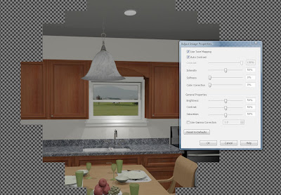
This next picture is of my preferred settings:
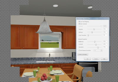
I like to leave the Brightness at 50%, move the Contrast up to 60 to 65%, and move the Saturation up to 70-75%. Make these adjustments first. Next, you might consider moving the Intensity down to 40-45%, and the softness up to around 30%. This finished raytrace took under 3 minutes:
Once you get your lighting right, you can then start experimenting with higher quality settings. However, make sure you have time, or you can set it to process overnight. If you are letting it go overnight, consider setting up multiple raytraces. Once you get one going, go back to your render camera, click Raytrace Current View, and start another one, with different settings. They will not raytrace at the same time, but once the first one is done processing, the next one will start. I have had 5 raytraces lined up at a time, and I don’t know if there is a limit.
One other thing to keep in mind, is the “Estimated Time Remaining” when a raytrace starts is not accurate. I have often found that number is initially about 10 times longer than it actually takes.
First thing you want to make sure of, is that all the lights in your model are turned off! Do this by going into “3D>Lighting>Adjust Lights”. Select the first light, scroll down to the last light, hold your shift key and click on the last light. This will “Group Select” all the lights at once. Then just click on the check mark in the box of any light fixture, and this will turn them all off at once. When you set up your raytrace, you will turn on just the lights in your scene. The reason for this (I learned the hard way) is if you have 165 lights on in your model, a “Quick” raytrace might take 7 hours, and if you only have 6-8 lights on, it will drop down to 5-6 minutes. Chief’s new raytracer will not be drastically slowed down by a complicated model, but it will be drastically slowed down by too many lights, even if they are on a different floor.
Before we adjust the light type, you should open your light fixture, go to the Material tab, select “Bulb”, click on “Plan Material”, select “Lighting, White”. Next, click on “Edit”, go to the “Properties” tab, Under “Material Class”, make sure “General Material” is selected, and move the slider for “Emmisive” all the way up to 100%. This will make the bulb on the light look like it is ‘glowing’ in a raytrace view, and look more like an actual light.

Next, some info about light source types. When a light fixture is placed in a plan from the library, it does not necessarily have the best settings for an interior raytrace, but so far, I have noticed they are set up to get a pretty good scene for renders. Any light you get from the library can be set to 1 of 3 different types of light source, regardless of what kind of fixture it is. This information can be found and adjusted by selecting a light fixture, either in plan view or 3D view, open the item, then go to the “Light Data” tab in the Dialog Box.
Chief has 3 types of light sources;
• Point light
• Parallel Light
• Spot Light
Point lights give a pretty even spread of light in every direction. They are the best type of light to light up a room in a render view, but I don’t like them at all in a raytrace view, because they give a big bright spot on the ceiling all around the fixture, like the light was shining back up towards the ceiling.
A Parallel light won't do you any good inside (aside from through openings). Parallel lights are infinitely far away. So, I won’t choose a parallel for an interior raytrace.
Spot lights seems to work the best for interior raytraces, but they require some adjustments.

Of course the first thing you want to do is to hit the drop down on “Type”, and select Spot Light. Next, Un-Check “Auto Intensity”, and move the slider up to 100%. This might be too high in certain scenes, and if so, you can back it off to around 80%.
The next item to adjust is the “Cut-Off Angle”. A Cut-Off Angle of 5º will give a narrow beam of light straight down to the floor. A Cut Off Angle of 60º will give a much wider beam of light, more like a real spotlight:


So far, for interior raytraces, I prefer to set the Cut Off Angle at 120º.
The next item we want to look at is the “Drop Off Rate”.
Quote: Dermot Dempsey “The Drop Off rate for a spot light controls how quickly the light drops off from the center of the cone to the outer edges of the cone.
Try experimenting with the values to see the effect. Place a single spot light in a room pointing down and leave the cut off angle at 60 degrees. A drop off of 7.5 means the light will drop off fairly quickly as it gets to the outer edge of the cone. Try setting it at 0 and you will see the same light at the outer edge as you do at the center. This will look more like the kind of spot light used in theater then in houses. Chances are that you will get the best effects with something greater then 0 but less then the 7.5 default.”
Here’s my explanation: In the pictures below, the first picture has the Drop Off Rate set at zero. This means that at the outer edge of the circle of light coming from this fixture, it has a clear (harsh) edge like a flashlight in the dark with a concentrated beam:

This next picture has the Drop Off Rate set at 2.0. This gives a much softer edge, but still allows you to see that the light is actually giving light to the scene, and a much more realistic look.

This third picture has the Drop Off Rate set to 6, which I think is too much, because the edge definition of the light is completely gone, so you don't get a feeling that these lights are real:

So, in this particular case, I like the Drop Off Rate set to 2.0.
This is not always the case, in some scenes, you will need to bump the Drop Off Rate all the way up to 10 or more to get soft edges with the lights. Here’s an example; In this office scene, The first picture has spots set with a Drop Off Rate of 2, and the edges on the light beams is too harsh. The second picture has the Drop Off Rate set at 8, and it looks much better:


However, this scene is also affected by the amount of light coming from the other fixtures & light sources. When you have additional light sources in the room, the edges of those spot light ‘beams’ get washed out a little bit, so you have to keep that in mind; if your edges are too sharp, and raising the Drop Off Rate doesn’t get it where you want it, you may need to add additional light sources.
Which brings me to my next subject:
Added Light Sources.
So far, I have found that in most cases, the lights I put in a model are not enough to properly light the scene enough for a good raytrace. When that’s the case, go to floor plan, go to “3D>Lighting>Add Lights” In a decent size kitchen, I will add 4 “Light Sources”, lined up behind the camera, across the room. I try not to put these in front of the camera, so that the light fixtures I have in the scene look like they are supplying the light for the room. I make these light sources point lights, uncheck “Auto Intensity”, and put the Intensity slider up to 75%. I also un-check “Casts Shadows” with my added Light Sources. The reason for this is I want my light fixtures to create the shadows for the scene, and I don’t want the extra light sources creating a whole bunch of extra shadows, making you wonder where their coming from. Again, the brighter these Light Sources are, the more they wash out or tone down the edges of the spot lights you are using.
Raytrace Settings:
When you are setting up your lighting, before you start a raytrace, start the raytrace wizard, and in the first window, select “Indoor”, and “Quick”. Click next, and put a check mark next to “Use Active Window Size”. You can get a faster raytrace by keeping the default 640 x 480 pixels, but in most cases, even with my 22” monitor and settings of 1485 x 852 pixels, the Indoor, Quick will finish anywhere from 50 seconds to 2 minutes.
The next thing to know, is a great new tool called the “Adjust Image Properties” tool. This tool works similar to a photo editing software, so you can adjust the raytrace after it’s complete. And, actually, you don’t have to wait until the raytrace is completed to start adjusting it. You can click the tool and make adjustments as it’s processing. If you get it looking like you want it and click OK, you can still go back later and reset it to defaults, if you like.
This picture below is a screen capture of the default settings:

This next picture is of my preferred settings:

I like to leave the Brightness at 50%, move the Contrast up to 60 to 65%, and move the Saturation up to 70-75%. Make these adjustments first. Next, you might consider moving the Intensity down to 40-45%, and the softness up to around 30%. This finished raytrace took under 3 minutes:
Once you get your lighting right, you can then start experimenting with higher quality settings. However, make sure you have time, or you can set it to process overnight. If you are letting it go overnight, consider setting up multiple raytraces. Once you get one going, go back to your render camera, click Raytrace Current View, and start another one, with different settings. They will not raytrace at the same time, but once the first one is done processing, the next one will start. I have had 5 raytraces lined up at a time, and I don’t know if there is a limit.
One other thing to keep in mind, is the “Estimated Time Remaining” when a raytrace starts is not accurate. I have often found that number is initially about 10 times longer than it actually takes.
Tuesday, November 17, 2009
X2 Terrain Basics
For a full size video, you can go to my website at http://indyblueprints.com/Free.aspx, or you can see my videos at www.ChiefTutor.com
Tuesday, October 6, 2009
Customizing Toolbars
One of the first things you want to do, before you start using Chief Architect for production work, is to customize the toolbars, so you can work more efficiently.
First, the Why's:
On a regular basis, while designing a house, I go into Chief's library, find an object, click on it, and place it into my plan. This process takes me about 45 seconds.
I know, you're asking yourself "Is it worth it for me to learn to do this, all to save myself 45 seconds?" Look at it this way: If I didn't have all these custom items on my toolbar, I would burn up 45 seconds each time I wanted to place one of these items on my plan. Since I place about 150 of these items per house plan, that's 6,750 seconds, or 112.5 minutes, or 1.875 hours per plan. If I am drawing 2 houses per week, that's 93 hours a year. That's equivalent to 2-1/2 weeks of work. If I am saving that much time, I can either work two more weeks each year and get paid for it, or I can take two extra weeks of vacation a year, for the same income!!
Here is a screen shot of the Default configuration that comes "Out Of The Box": (Click picture for a higher resolution)
 As you can see, it has two rows on top, and one row to the side.
If you look closer, those rows are broken into "Toolbars".
The top row is broken into two toolbars; the first has your "open", "save", "Print", "Send To Layout", "Default Settings", "Preferences", "Active Layerset Control",
"Layer Set Management", "Library Browser", & "Help".
The next toolbar has your different toolbar configurations, to include "Default Configuration", Terrain Configuration", "Kitchen & Bath Design", "MEP", "Space Planning", "Plan Detailing", and "CAD" configurations.
The bottom row is one toolbar, with all your "Building" tools: walls, doors, windows, cabinets, electrical, stairs, floor tools, roofs, framing, slabs, shapes, dimensions, text, cameras, and change floor tools.
Along the right side are two toolbars; the first is different window view tools, and the second are your preference tools.
Although you can create construction drawings & house designs with this toolbar configuration, if you want to be more efficient, draw houses faster, and therefore make more money, it makes sense to customize the toolbars to maximize the program for the way you use it.
Chief Architect X2 uses the "Drop Down Menu" style of toolbars. Call me Old School, but I don't like having to use the drop downs, I prefer to have a tool right there staring me into the eyes, where I can see it, recognize it, and click once to use it.
In addition to that, Chief Architect X2 has a very extensive library of 3D object to use on your houses. The library is so large, that it is sometimes very time consuming to search through it to find the object you are looking for. If you are like me, there are several library objects that you use on a regular basis in all your homes; sinks, washer & dryer, tub/shower combo unit, beds, dressers, tables, etc.
So, I have placed all my most common tools, and my most common library objects on my toolbars.
Keep in mind that Chief will only let you place a maximum of 80 Toolbars on your desktop, but it will allow you to place an unlimited number of tools on those toolbars. I will go into how to do this down below.
Here is the custom configuration I use:
 If you look closely, you will notice I added 8 new toolbars, which include about 70 different tools. Along the top I have my various CAD tools, my dimension tools, my "Break Wall" tool, and a few others.
On the right side, I have placed my different Library Objects, categorized into like groups; Electrical Objects, bed room/living room furniture, bathroom/HVAC fixtures, & kitchen appliances.
Next, The Hows:
The first thing I want to show you, is how to make a custom toolbar configuration, so you can switch to it at anytime.
First, go to "Tools>Toolbars & Hot Keys>Customize Toolbars". Go to the "Configurations" tab, highlight the "Default Configuration", and click the "Copy" button on the right side. This will bring up a window that wants to know where you want to save this copy, and what you want to call it. It will automatically open the right folder, but just in case, it is in the "Toolbars" folder, which is in the "Chief Architect X2 Data" folder.
Next, the name. I called mine AB Configuration (A for Allen, B for Brown), then click "Save". The next thing you want to do, is highlight your new toolbar configuration, and click "Switch To". This will get you using the new configuration in Chief. This window will still be open, which you want. Now we start to customize.
Lets first start with some CAD tools: Go to the "Tools" tab, and highlight "All Views". We'll start with some line tools: Click once in the middle box, which is titled "Main Toolbar Buttons", and type the letter "L" on your keyboard. This will jump you down to the tools that start with the letter "L". (By the way, this is a shortcut that works throughout Chief).
Next, click on the tool titled "Line Tools". In the box on the right, which is labeled "Child Tools", you will see the child tools associated with the parent line tool. Let's start with the "Draw Line" tool; Click on the "Draw Line" tool, and drag it onto a blank spot on your upper toolbar area. This will place a new toolbar with that tool on it. Next, click on the "Sun Angle" tool, and drag it over to the same spot, and drop it right on top of the "Draw Line" tool. This will place the sun angle tool on the same toolbar. Remember how I said that Chief will only let you have 80 toolbars?
Next, click again in the middle box, and type the letter "B", and highlight "Box Tools". Go into the "Child Buttons" area, and drag the "Rectangular Polyline" over and drop it onto the other two items you already placed. You can then place any of the other child tools you want access to with them. Next, do the same for the circle tools, "Point Marker", "Place Point", and the "Delete Temporary Points" tools. I would also place your dimension tools on this same toolbar; "End To End" dimension, "Point to Point" dimension, and the "Interior" dimension tools.
One other big tool you want to add is you "Break Wall" tool. Drop that tool just to the right of your wall tools on the main toolbar on the second row down from the top. This item used to be easier to access in previous versions of Chief than it is now, so this one is a must.
Next, the Library Objects: This step is a little bit different method than above. Instead of going into the library and just dragging the objects onto the toolbar, you have an extra step, so let's get started:
Again, go to "Tools>Tools & Hotkeys>Customize Toolbars". In the "Tools" tab, click on "All Views". Next, click in the middle box (Main Toolbar Buttons), and type the letter"P". This will shortcut you down to the tools starting with "P". Look for the tool labeled "Place Library Object". Now, drag this tool down and drop it onto an open space on the right toolbar area. Repeat this step 6-8 more times, dropping the same tool right on top of itself each time. By doing this, you will create a toolbar that has 6-8 potentially different objects from your library. Click "Close".
The next step is where the magic happens: The first thing you want to do is to click on the top object on this new toolbar. A window will pop open titled "Library Object Button Specification". The reason for this, is that you must now assign a library object to this button. So, click the "Library" button near the top right. At this point, you need to navigate through you library and choose something to assign to this button. Let's start with furniture. One of the most common items I place in a plan are beds. First pick a King size bed, and click "OK". This will close the library and bring you back to the "Library Object Button Specification" window. Next, you need assign a "Button Icon Choice". Never use the default, pick either Automatic 1, or Automatic 2, then click "OK". Repeat those steps for the next 6-7 object buttons, and assign Queen size bed, double, single, dining room table, maybe some dressers.
You can then repeat the same steps to make a toolbar for your most commonly used appliances, another for your most commonly used light fixtures & smoke detectors, and then another one for plumbing fixtures, etc.
I hope this blog had some useful information for you! Please take a look at my website for some free online Chief Architect training videos, and check back here often (or subscribe) for more great and useful Chief Architect How-To information!
Subscribe to:
Comments (Atom)